Modular Mixer
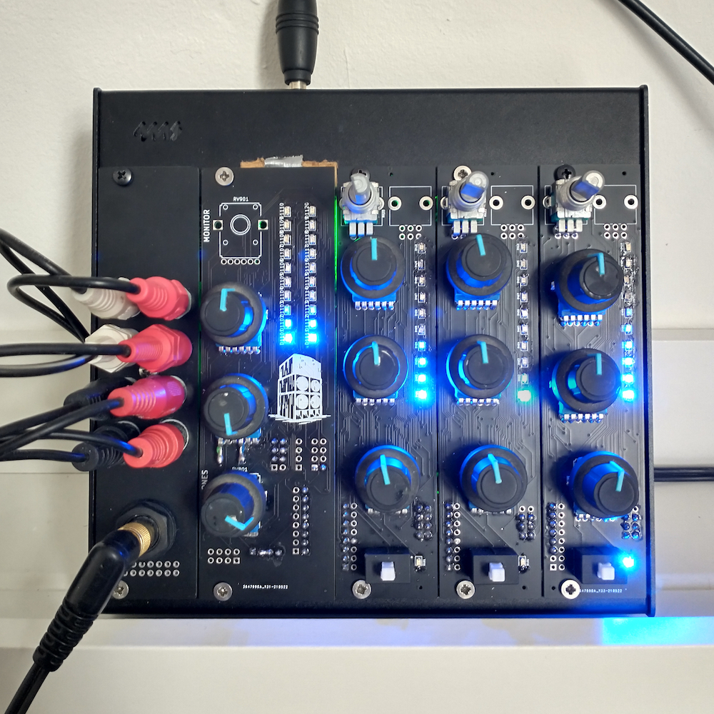
Eurorack compatible modules for a stereo DJ mixer, with 2.54mm header connections for XLR and line level outputs, cue-ing system with a headphone driver, and VU meters.
Contents
- View on GitHub
- Overview
- 2 Band Isolator Channel | KiCAD Project
- Main Channel | KiCAD Project
- Power Supply
- Troubleshooting
- Future Work
Project Overview
Inspired by Eurorack modular synthesizers and the boutique mixer market, the project aims to design and build a simple and customisable DJ mixer. Ripping the faceplate off most mixers the design is already fairly modular, but only in that mixer's specific form factor. Taking the Xone:92 as an example, each of the channels are identical boards feeding their outputs onto mix buses to be summed, so with a custom case it could be expanded to an N channel mixer, with custom designs added as additional channels [Ref 1].
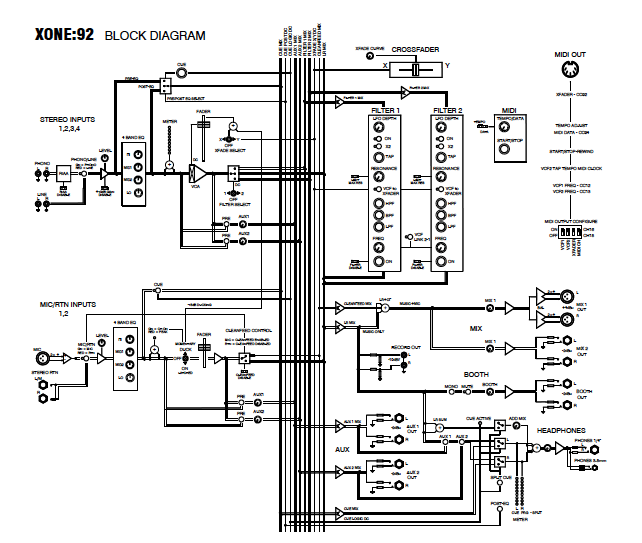 Ref 1 - Xone:92 mix bus (Xone:92 Service Manual AP5296 Page 9)
Combining this idea with the Eurorack ethos, the project aims to build a fully customisable system, with N channels that can be mix and matched between isolators, filters, fx units, and traditional eurorack modules
Initial Design
Eurorack compatible modules for a stereo DJ mixer, with 2.54mm header connections for XLR and line level outputs, cue-ing system with a headphone driver, and VU meters.
The design is op-amp based, with filters implemented as 12db/oct active inverting filters, 10 kohm output impedances, and buffered potentiometes acting as voltage dividers for the controls
The signal path of the initial 2 band isolator channel design is as follows
- a line level stereo input
- apply a 5x gain to it
- pass it through a signal trim pot
- split the signal with low pass and high pass filters
- a potentiometer for the low pass, and a potentiometer for the high pass allow the signal to be shaped
- the remaining signals are summed
- the summed signal is sent to the channel's outputs; a potentiometer controls how much is sent to the main bus, a button controls whether the signal is sent to the cue bus, and the full signal is sent to the IC controlling the LED level meter
The signal path of the main channel is simpler, summing together the different audio buses and then outputting the combined signals
- cue, aux, and main busses enter summing amplifiers; the 10k resistors on the channel outputs ensure that the channels are equally summed
- the main signal is fed into the LED level meter, the cue summing amplifier (via a voltage divider), to a line level buffered output, and a balanced output circuit
- all of these outputs have buffered voltage dividers controlling the level
- the headphone output is op amp based, but when built with a high current op amp such as the Texas Instruments OPA1688 (75mA / channel), it can provide more than enough power to drive monitoring headphones
Isolator Channel | KiCAD Project

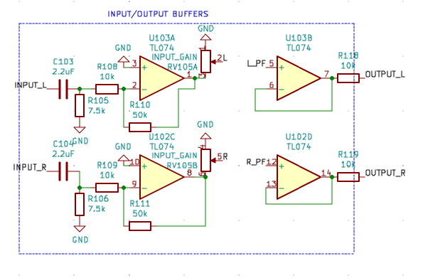 Input and Output buffers
The channel input begins by applying a high pass filter to the signal, and amplifying it with a gain of 5. This amplified signal is then trimmed by a voltage divider before being fed into the isolator circuit.
The amplified signal is then fed into two filters, a low pass and a high pass. Both filters are 12dB/octave filters with identical cut off frequencies i.e. the isolator crossover frequency. As both filters have the same cut off frequency the overall frequency response should be fairly flat.
The output levels of these two filters are then fed into potentiometers to allow a user to reduce the volume of either the high or low passed signals while mixing. Once the level for each filter output is set, the 2 signals are summed together to recreate a single audio signal. This is done independently for both the left and right signals, with dual gang potentiometers ensuring that the filters outputs can be controlled in stereo.
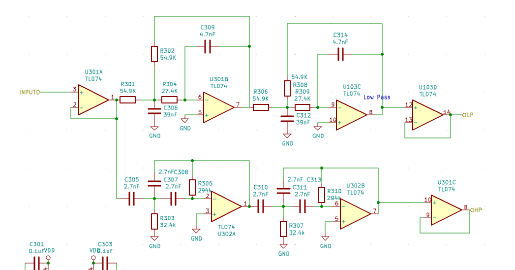 High and Low Pass filters
 Post Isolator
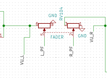
Post isolator the signal is split again. The complete post isolator signal is fed into the VU meter for visual feedback, sent to the 'fader' (in this case a rotary potentiometer) for adjusting the level of the signal in the mix, and also to the cue bus (if the cue button has been pressed!).
In the example schematic the auxillary send is also connected to the prefader signal, to use this with external effects it may be more useful to connect this post-fader, or to add a switch or jumper to change between pre/post.
Ideally, a Texas Instruments LM3916 would be used to visualise the audio signal and the schematic is designed for this. However, in the non-ideal world TI have discontinued all but the linearly scaled LM3914, and only manufacture it in an awkward 20 pin PLCC package. The layout and gerbers use the PLCC LM3914 but an alternative circuit should be considered for true logarithmic VU meters.
There's nothing notable in the VU schematic, it is almost taken directly from the LM3916 datasheet, only with an additional summing amplifier to convert the stereo signal to mono.
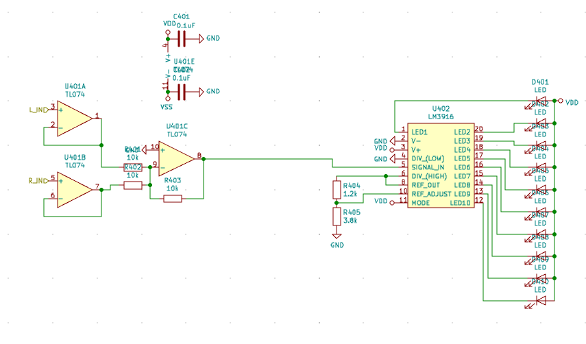 VU meters using LM391x
Finally, and crucially the output headers. Each channel includes a standard 16 pin eurorack power header to provide +/- 12V, 5V, and GND. The Eurorack connector also has 4 additional pins that are typically used for Gate and Control Voltage (CV) signals, which could have been repurposed as bus channels, but would have added compatibility issues if the mixer was used in the same rack as standard Eurorack modules.
To keep in spec with other modules, a new 8 pin connector is used, with stereo connections for: input, main output bus, headphone cue bus, and an aux send bus.
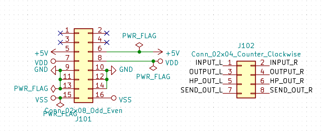 Channel output headers
All in all it's a fairly straightforward way to mix, but there's definitely room for some improvement:
-
Current potentiometer is the Bourns PTV112, the shaft wobbles a bit, and it doesn't feel well made
-
There's only just enough space at the top and bottom of the board for mounting rails, metal mounting rails can cause a short circuit
Main Channel | KiCAD Project

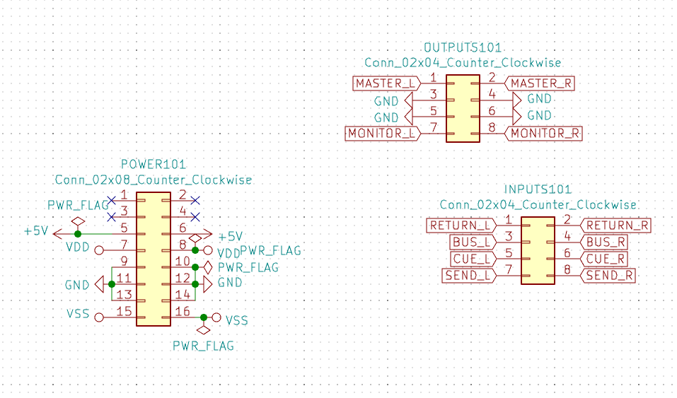 Main Channel Connectors
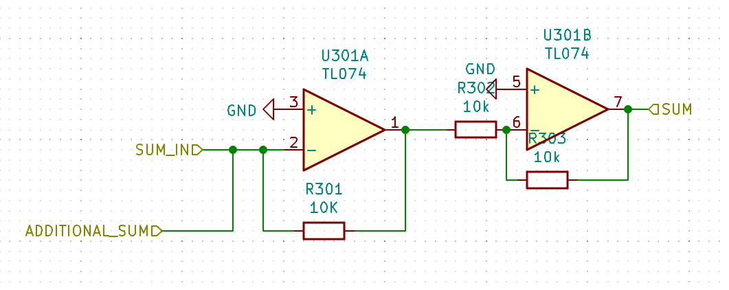 Summing Amplifier
The main channel takes inputs from the various busses and sums them, as each output has a 10k resistor on the end of it any number of channels can be connected to the amplifer and they will be summed equally.
The summed main bus is then sent to two buffered voltage dividers to allow a user to set two independent output levels: monitor, and main outputs. Typically one would be connected to a small monitor speaker for the DJ, and the other to the sound system.
The previous two signals are both unbalanced and line level, which is probably fine for use at home, but a balanced output is usually needed for a big rig. So, the master output is also connected to a circuit that generates the required balanced signal. On the example schematic, all outputs are to 2.54mm headers and need connecting to RCA / XLR sockets.
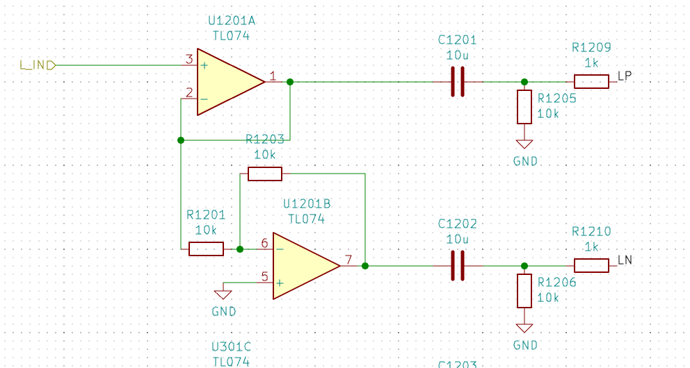 Balanced Output
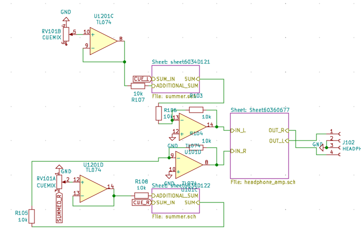 Cue summing
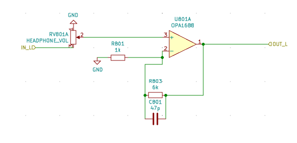 Headphone Amplifier OPA1688
The cueing circuit takes the sum of everything on the cue bus, plus an amount of the main determined by a voltage divider. This allows a DJ to add N% of the main output into their headphones to help mix when there is a poor/non-existent monitoring set up.
Having originally built a transistor push-pull amplifier to drive the headphones, I've found that it's simpler and easier (JLCPCB will even fit it) to use a high current op-amp that has built in short circuit protection - the Texas Instruments OPA1688. Inserting/removing headphones shorts the output and has caused me transistor problems.
The VU meter on the main channel is only for the main mix bus, and is unaffected by any of the controls on the module. It follows the same LM391x schematic as the isolator channel, but with a seperate meter for each stereo channel rather than a summed signal.
Again, it works, but there are some changes that could be made:
- Upgrade the potentiometers
- Alternate LED driver for the VU meter. No modern chip exists, so either swap to a SOIC-16 LM3916 clone or use a microcontroller
Power Supply
Thanks to the modularity of Eurorack any modular power supply can be used! In this design a custom one is built, but all it does is take a 18-36V DC signal, run it through a DKA30B-12 DC-DC converter to provide the required +/-12V power rails. A ST L7805 is used to generate the 5V rail.
An additional feature of this custom PSU is two phono preamps, which perhaps should be moved to the channel in future revisions.

Troubleshooting
An overview of issues I encountered whilst building this prototype
First mistake was to order my parts from Mouser, 2 weeks later they’ve been FedEx’d from Texas and it’s time to discover the hardware mistakes.
Clearance at the top and bottom of the PCBs
There's not quite enough clearance on the PCBs to the rack rails. I've had to wedge a piece of cardboard in at the top of the main channel to stop it from shorting against the rails.
PSU Board
Soldered the Meanwell DC-DC Converter to the PCB and hooked up a power supply to the input. The 12V, -12V, and 5V LEDs lit up briefly, and then turned off. The PSU showed 19V and 0.00A.
Replacing the underspecced 1N4148W diode with a short fixed this. The DC-DC convertor will survive reverse polarity so this diode was unecessary to start with.
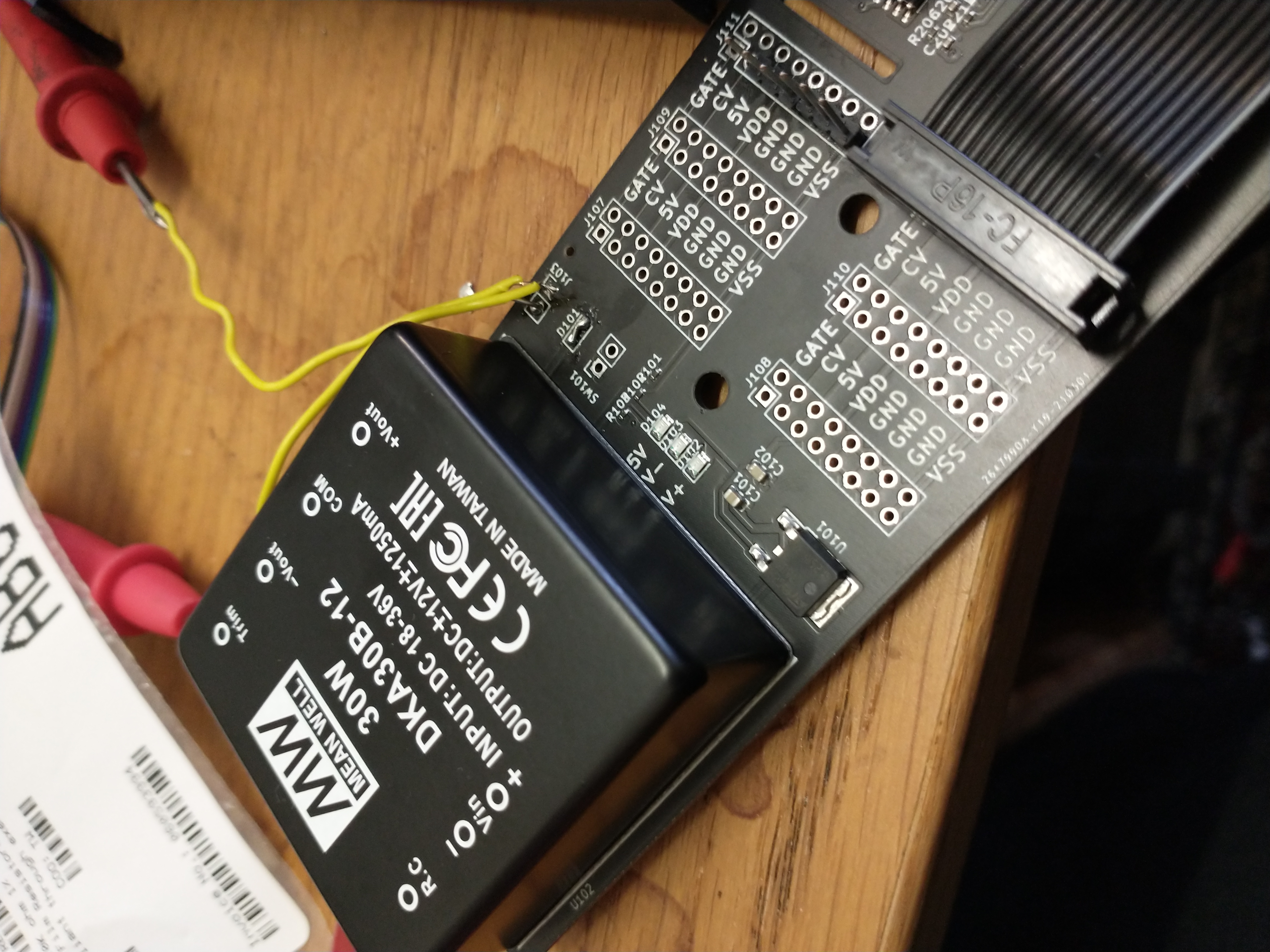 PSU
PSU
LM3914 PLCC Package
During the first build the PLCC package wasn’t soldered correctly. Supposedly a package that is socket and SMD compatible, but it’s a definitely a pain to do by hand.
Need to desolder this one and redo it with a bit more care.
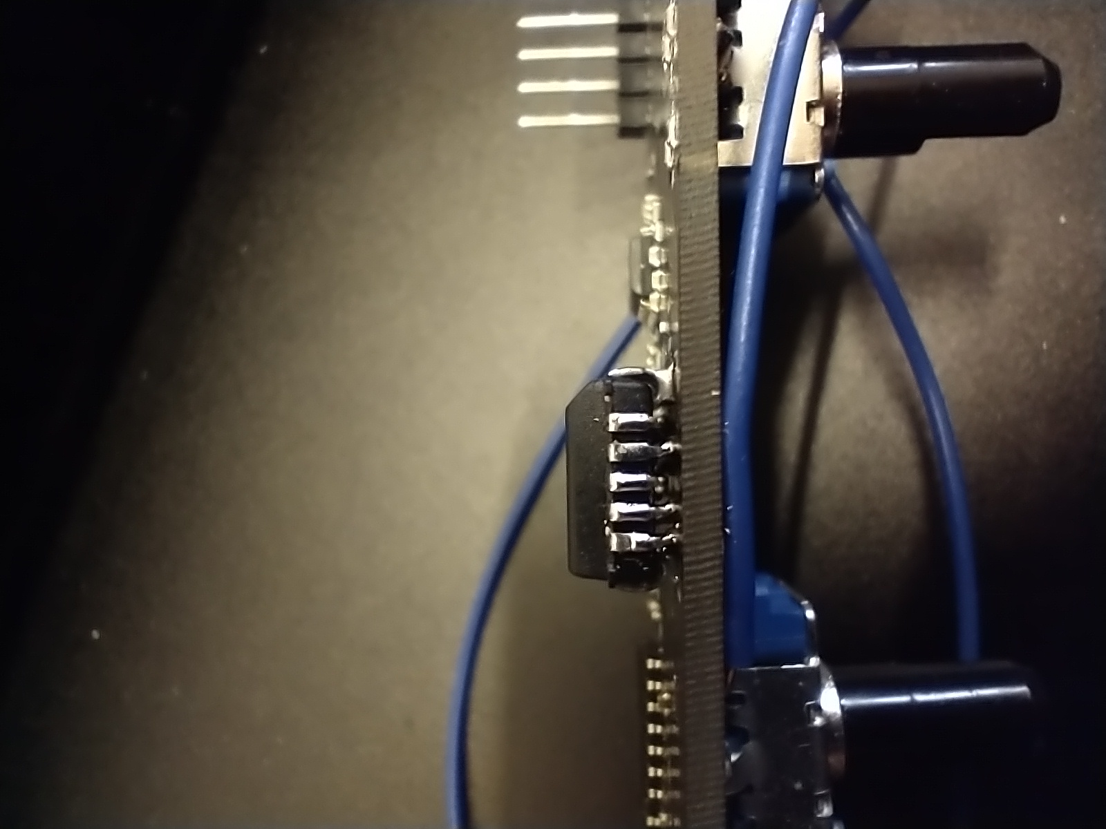 PLCC
PLCC
note - not sure I’d use this IC again.. although the alternatives are a uC with an ADC, or an array of OP amps with a resistor ladder.
PLCC package has a different pin order.. pins are all in the wrong place on my footprint
LM3914 Forgotten VDD Connection
The schematic for the VU meter is missing a power connection across the LED anodes. Need to think of a tidy way to add a wire across for the first boards.
Untested due to the dodgy PLCC soldering mentioned above.
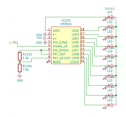
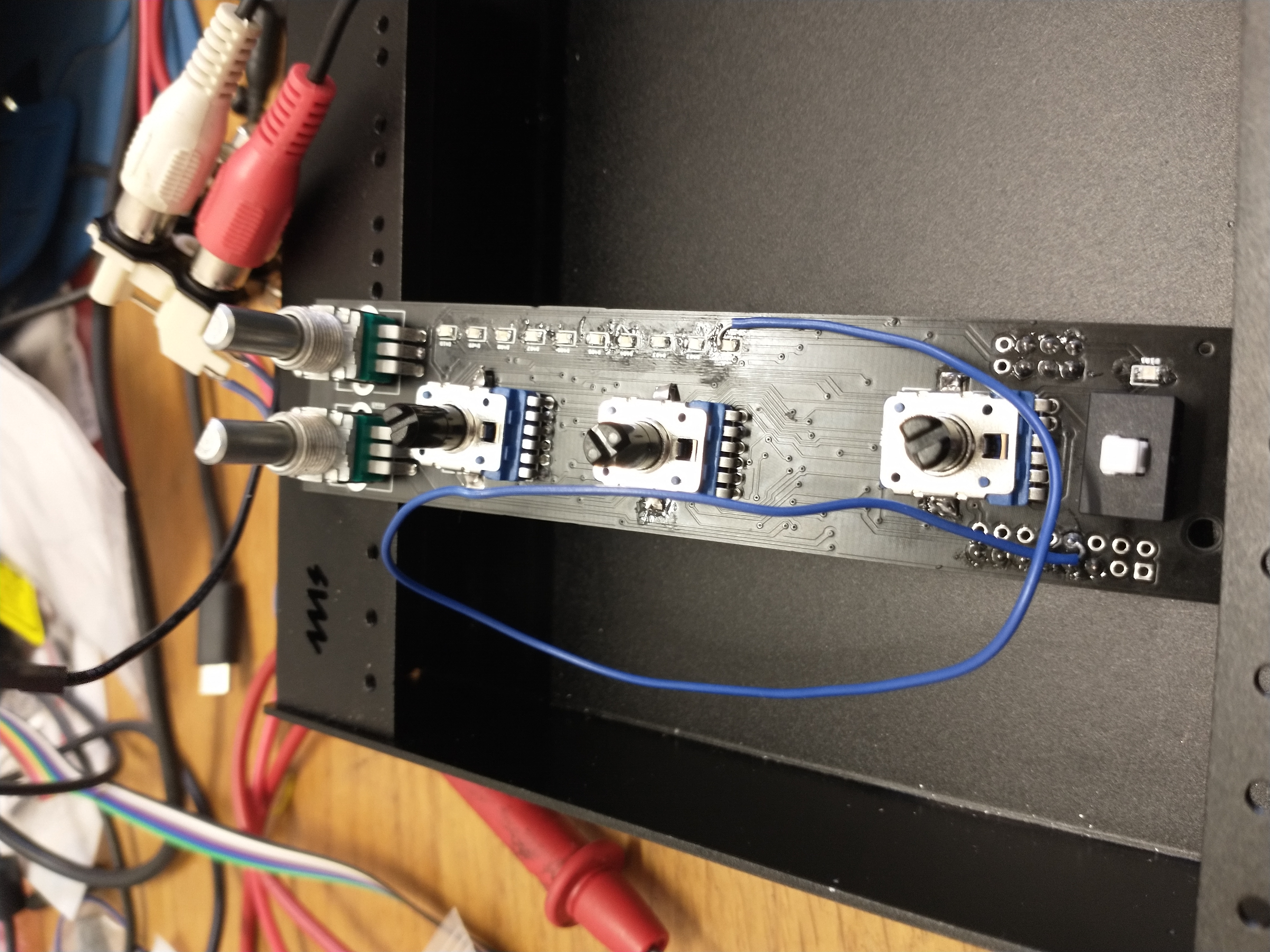
SMD resistors on unassembled side
After checking and approving the Schematics, PCBs, and component list, I noticed that R103 and R104 (10k resistors) were on the front side on the PCB and were not going to be assembled in the factory.
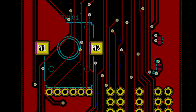 R103 and R104
Ordered some 10k 0402 resistors and manually fitted them
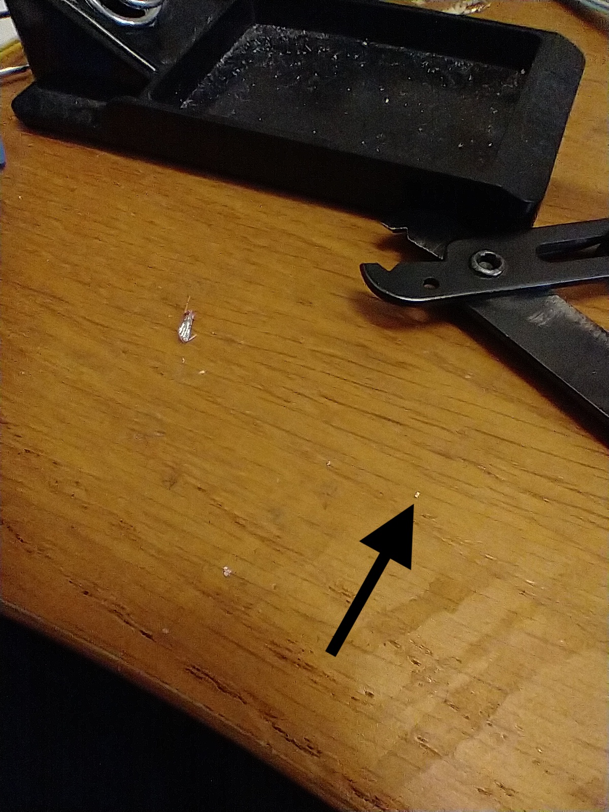
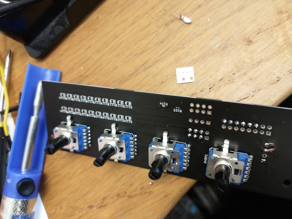
Input Gain / Send Pots are Anti-Clockwise
Pins 1 and 3 need swapping. The input gain maxes out at only 2x which isn’t a huge amount. Maybe 50k Input Gain pots to crank the tracks.
Cue switch is reversed
All cue switches need to have the same orientation, plus the LEDs aren’t working
The switch is a pretty bad solution. An Analog Switch IC may be a better option. One SPDT switch/button can control the ICs. Example IC: £0.0451 BL1551
Channel PCBs are too short
The channel PCBs are too short and the screw holes don’t line up perfectly. It’s possible to screw it in, but it doesn’t quite fit, and leaves very little clearance for components.
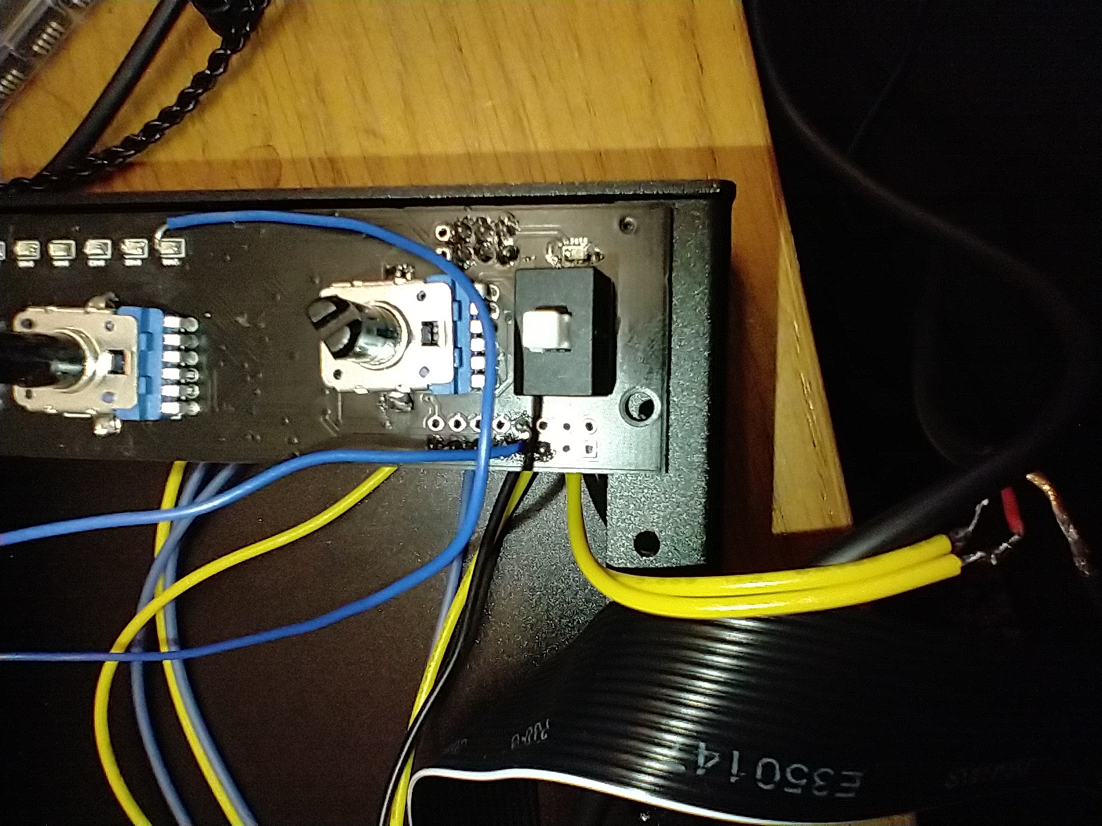 Short PCBs
Headphone Amp - PNP the wrong way round
Plugging in the master channel can result in some magic smoke - the PNP transistors in the headphone amplifier are the wrong way round. Some visible damage on Q803
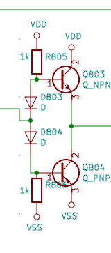
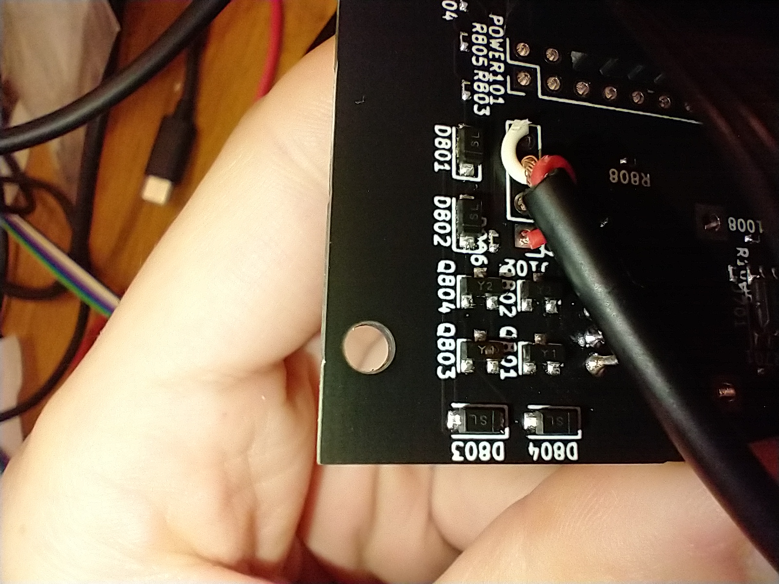
Actually transistor pins are all incorrect
Wiring through hole transistors on flying wires results in a working headphone amplifier
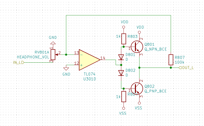 Transistor Pinout
Cue / Master mix fader doesn’t work
This is a stupid circuit - not sure what I was thinking 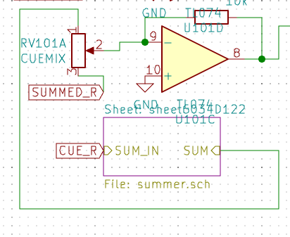
No summing resistors on the updated CUE/MASTER knob
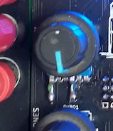
Adding resistors between the potentiometer and summing input solves this, however the profile ends up curved and can never reach zero master due to the virtual ground at the summing input
 Additional Resistors
Future Work
As it stands, it's a working mixer that I use day to day. However, there are a few changes for future versions:
- Different pots, the current PTV112s are a bit flimsy. Ideally I'll add a second footprint for a choice of cheap vs quality. Alps RK27 are the hi-fi standard but may be too large to squeeze into a 6hp channel.
- Move pots to feedback resistors. This will remove the need for a lot of the buffer amplifiers and reduce the chip count
- With a reduced chip count the phono stage should definitely be added to the channels
- Add kill buttons to isolators. Instakill vs turning the potentiometer.
- Alternate VU driver. The linear LM3914 isn't ideal, neither is the gigantic PLCC package.
- Replace all filters and attentuators with VCF/VCAs. Then additional control signals can be fed in to really integrate it into a modular system. JLCPCB stock LM13700 so assembly is still simple
- Additonal channel types! Faders, filters, EQs, FX.. all are possible